Shed slab design · Tenambit NSW
In short: The client planned a steel-framed shed in Tenambit NSW beside a Hunter Water sewer line, with part of the slab inside the sewer's zone of influence. We designed a mesh-reinforced slab with edge and internal beams, with 450 mm piers on the sewer side taken at least 600 mm below that zone. The drawings were issued for approval.
- Service
- Shed slab design
- Location
- Tenambit NSW
- Completed
- September 2026
- Structure
- Proposed detached steel-framed shed on a concrete slab
- Asset
- Existing Hunter Water sewer line beside the shed (a build-over-asset case)
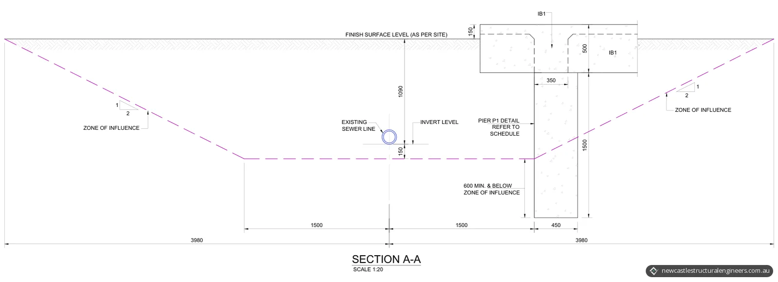
- Zone of influence (as drawn)
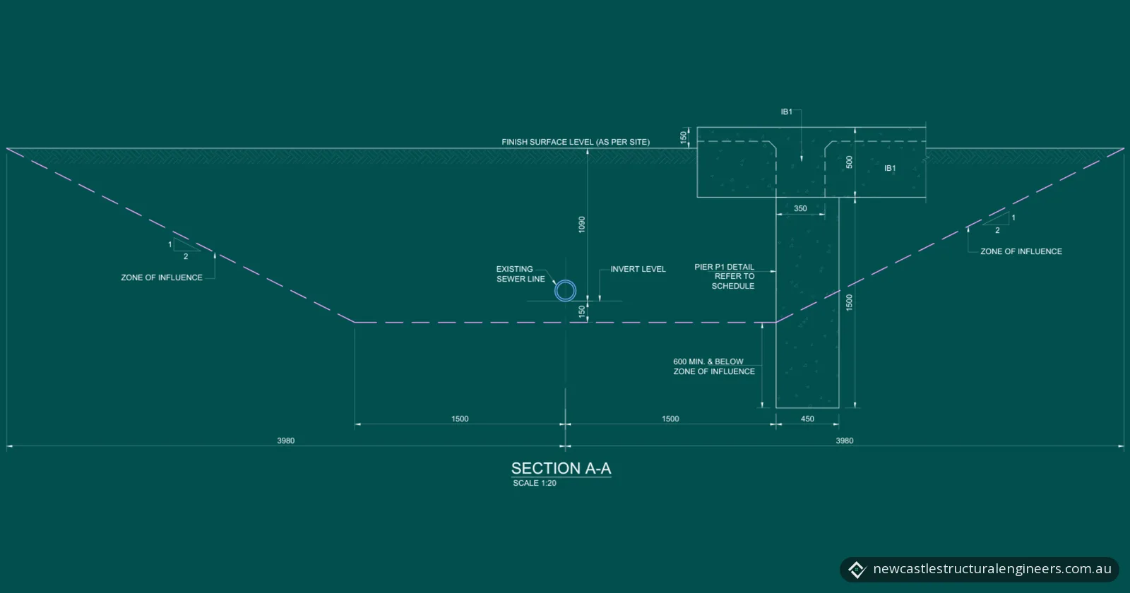
- From 150 mm below the sewer invert, 1500 mm either side of the pipe's centreline, rising at 1 vertical to 2 horizontal to meet the surface 3980 mm from the centreline
- Piers
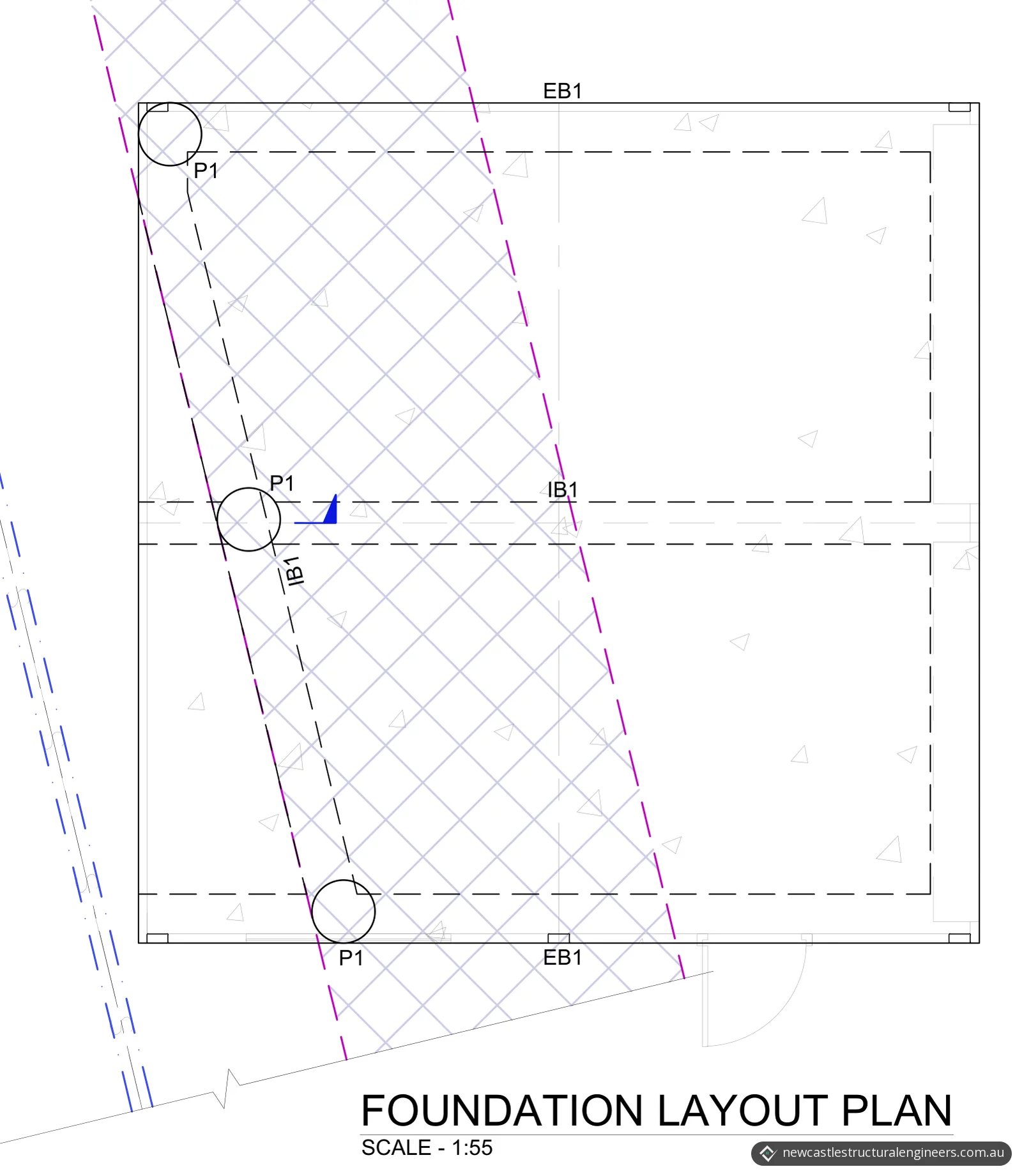
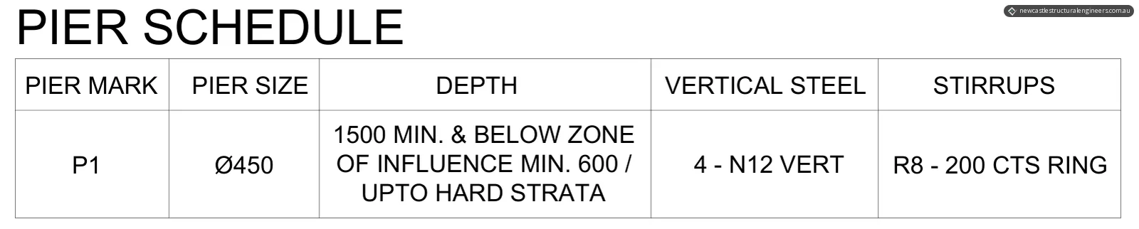
- Three P1 piers on the sewer side, 450 mm diameter, four N12 vertical bars and R8 rings at 200 mm centres
- Pier depth
- 1500 mm minimum and at least 600 mm below the zone of influence, up to hard strata
- Beams
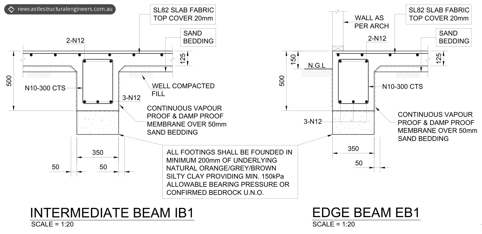
- Edge beams (EB1) and intermediate beams (IB1), 500 mm deep and 350 mm wide
- Slab
- Slab on grade with SL82 mesh at 20 mm top cover, over a vapour-proof and damp-proof membrane on 50 mm of sand
- Soil class designed for
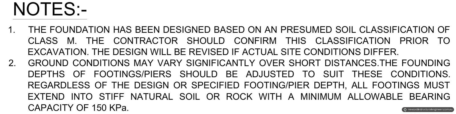
- Class M (presumed, to be confirmed by the contractor before excavation)
- Bearing capacity
- At least 150 kPa allowable, in stiff natural soil or rock
- Concrete
- f'c 32 MPa at 28 days, unless noted otherwise
- Main standards referenced
- AS 3600-2018 (concrete), AS 2870-2011 (preparing the sub-base for slabs on ground)
The brief
The client planned a detached steel-framed shed at a property in Tenambit, in the Hunter region of NSW. An existing Hunter Water sewer line runs past the shed, outside the slab, and part of the planned slab fell within the sewer's zone of influence. The job was a build-over-asset case.
The client needed structural drawings for the shed slab and its footings, for approval before construction.
Why it needed a structural engineer
Hunter Water's general guide is to keep buildings and structures at least 1.5 metres from its assets. Where that isn't possible, it says it may be able to assess options for building closer to or over some assets. Its assets must stay accessible, and they cannot be buried, demolished, relocated or altered without its approval.
The options Hunter Water lists for protecting an asset include installing footings or piers under or around it, moving the building or structure further away, or relocating the asset, which is generally at the property owner's cost.
The structural drawings for this shed set out where the sewer's zone of influence sits, which part of the slab it crosses, and how deep the piers on that side go to get below it.
What we designed
The drawing set has six sheets: a cover sheet, general notes, a site layout plan, a foundation layout plan, section details, and a section through the sewer and the nearest pier (Section A-A).
The sewer's zone of influence
- As drawn. Section A-A draws the zone of influence from a level 150 mm below the sewer's invert, extending 1500 mm either side of the pipe's centreline. From there it rises at 1 vertical to 2 horizontal until it meets the finished surface, 3980 mm from the centreline.
- Depth of the pipe. In the same section, the sewer invert is 1090 mm below the finished surface level.
- On plan. The foundation layout plan marks the zone of influence and hatches the zone of influence area where it crosses the side of the slab nearest the sewer.
Piers on the sewer side
- Layout. Three piers (P1) sit along an intermediate beam that runs parallel to the pipe, on the side of the slab nearest the sewer.
- Size and reinforcement. Each pier is 450 mm in diameter, with four N12 vertical bars and R8 rings at 200 mm centres.
- Depth. The pier schedule sets the depth at 1500 mm minimum and at least 600 mm below the zone of influence, up to hard strata.
- Distance from the pipe. In Section A-A, the face of the pier is 1500 mm from the sewer's centreline, and the pier is taken down past the zone of influence line.
Beams and slab
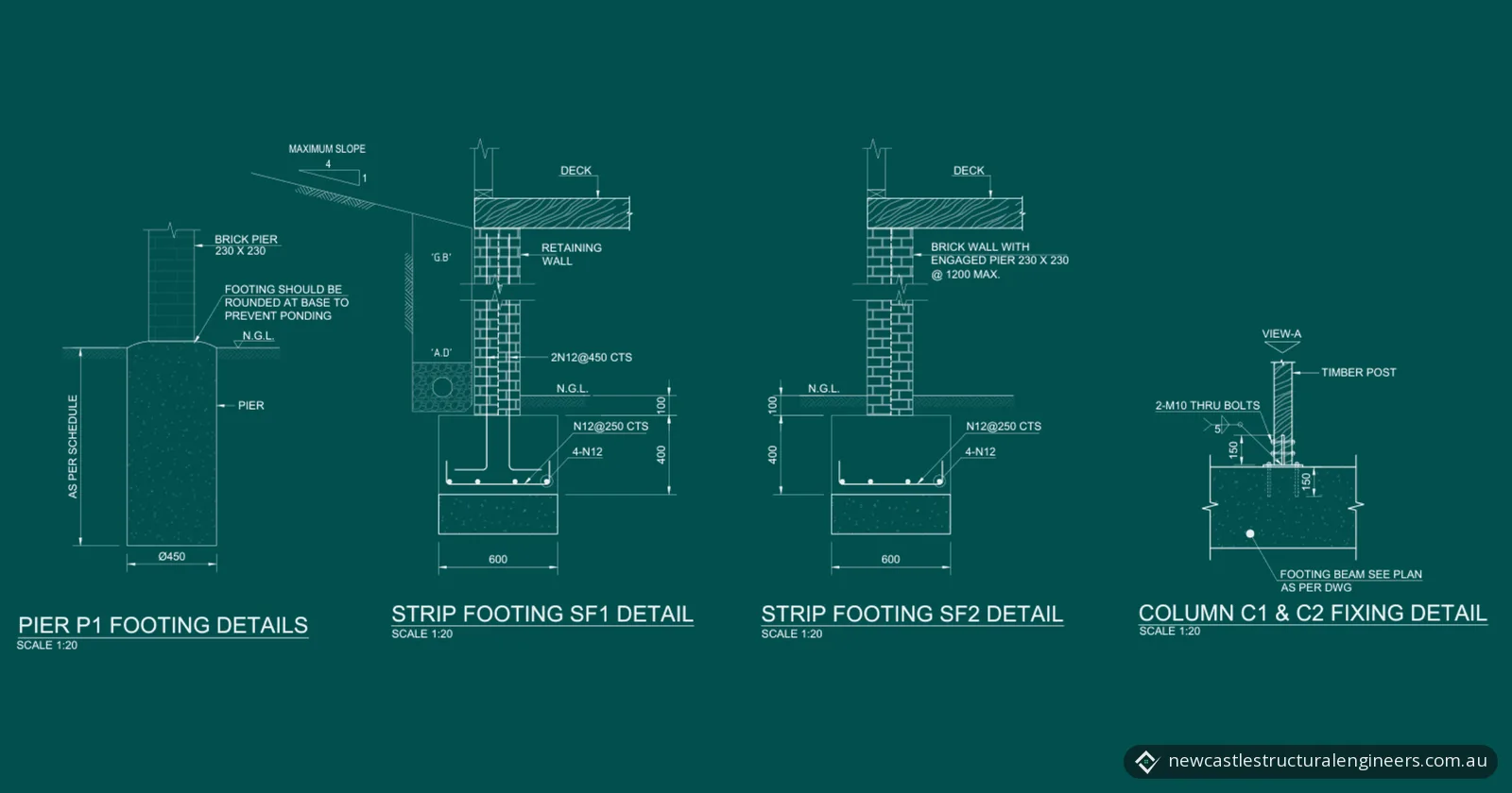
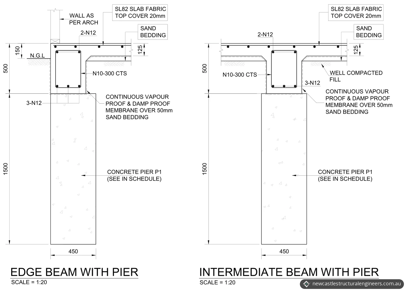
- Beams. The edge beams (EB1) and intermediate beams (IB1) are 500 mm deep and 350 mm wide. Each has three N12 bars at the bottom, two N12 bars at the top and N10 ligatures at 300 mm centres. The edge beam stands 150 mm above natural ground level.
- Beams on piers. Where a beam meets a pier, the details show the beam bearing directly on the 450 mm pier.
- Slab. The slab on grade carries SL82 mesh at 20 mm top cover. It sits on a continuous vapour-proof and damp-proof membrane over 50 mm of sand bedding, with well-compacted fill beneath.
- Typical details. The set also includes typical details for L and T beam intersections and for a service pipe passing through a footing.
Concrete and slab preparation
- Concrete. Concrete quality follows AS 3600-2018: a characteristic compressive strength (f'c) of 32 MPa at 28 days, a maximum slump of 75 mm and a maximum aggregate size of 20 mm, unless noted otherwise.
- Sub-base. The sub-base for the slab on ground is prepared in line with AS 2870-2011. Topsoil containing humus and vegetable matter is cleared from under the slab, to at least 100 mm.
What has to be confirmed on site
The design depends on the ground, so the drawings list what the builder and the client must check:
- Soil class. The foundation is designed for a presumed Class M soil classification. The contractor should confirm it before excavation, and the design will be revised if actual site conditions differ.
- Founding. Ground conditions may vary significantly over short distances, so founding depths should be adjusted to suit. Whatever depth is specified, all footings must extend into stiff natural soil or rock with a minimum allowable bearing capacity of 150 kPa. The beam details call for every footing to be founded in at least 200 mm of the underlying natural orange, grey or brown silty clay, or on confirmed bedrock, unless noted otherwise.
- Groundwater. If groundwater is found at the design depth of the beams, footings or piers, the contractor must contact the engineer for advice.
- Geotechnical check. The client or their representative is to engage a geotechnical consultant to evaluate and verify the foundation soil conditions before construction starts.
The result
The client received the six-sheet drawing set, issued for approval. It gives the builder the size, depth and reinforcement of the piers on the sewer side, the beam and slab details, and the checks to make before and during excavation.
The general notes state that the drawings are subject to approval by the relevant local authority or council before construction, and that no work is to start until written authorisation to proceed has been issued.
Building near a sewer in the Hunter?
Our structural design service prepares structural drawings and details, including footings and beams. We work across Newcastle and the suburbs listed on our service areas page. Send us your shed or building plans, a site plan showing where the sewer runs, and any asset location plan, Before You Dig information or geotechnical report you have. You can request a quote online or call 02 4091 1900.
Photos and drawings
From the report
Sample pages from what the client received (personal details removed).
Frequently asked questions
Can you build a shed over or near a Hunter Water sewer?
Sometimes. Hunter Water says you may be able to build over or close to a sewer main if certain conditions are met. It assesses the building plans and identifies options that protect its assets, such as footings or piers under or around the asset.
How do you find out if Hunter Water needs to assess your plans?
Start by checking what is on your property. Hunter Water points to Before You Dig Australia for the location of underground services, and offers a detailed asset location plan if you need more. Then submit your site, floor and elevation plans through its Property Self Service Portal. If your project is close to or over its assets, Hunter Water assesses the plans and tells you whether a Build Over Asset Application or a Development Assessment Application is needed. If you're unsure, it says to submit your plans and it will let you know.
How close can you build to a sewer manhole in the Hunter Water area?
Hunter Water calls a manhole a maintenance structure. It gives access to the sewer pipes and sits directly above the sewer main. Hunter Water says to keep your project at least 1.5 metres from the centre of the maintenance structure.