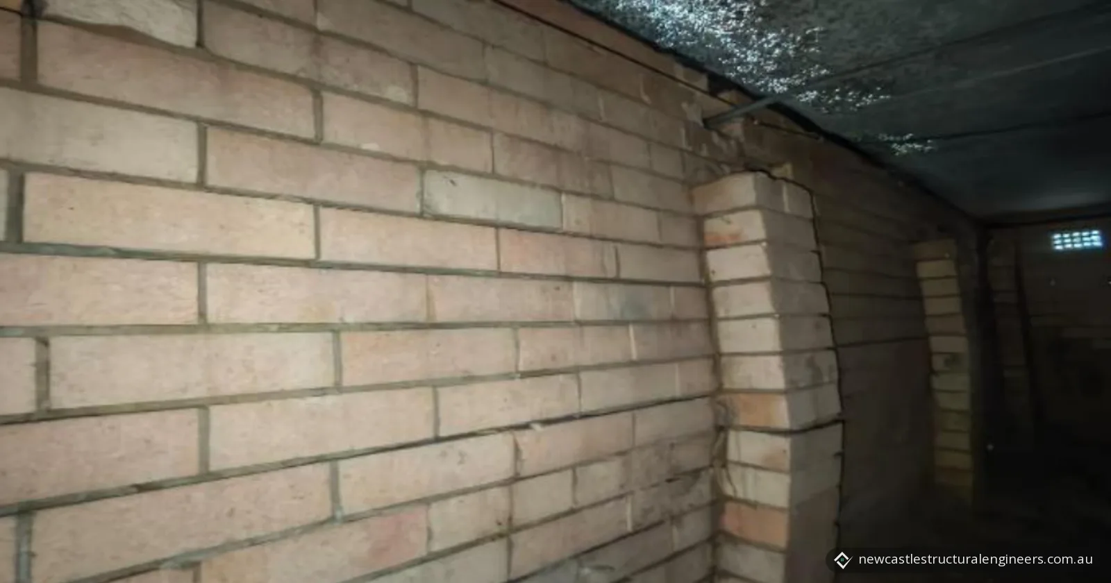
Structural design and drawings · Cardiff South NSW
In short: Our client in Cardiff South needed structural drawings for alterations and additions, including partial demolition. We designed piers, strip footings and slab beams for a Class E (extremely reactive) site, a timber floor and roof framing, and the fixings to the existing structure, in a 19-sheet set that gives the builder the details to work from.
- Service
- Structural design and drawings
- Location
- Cardiff South NSW
- Completed
- September 2026
- Scope
- Alterations and additions, with part of the existing structure removed
- Site class
- Class E (extremely reactive), from the site's geotechnical classification report
- Founding
- Design allowable bearing capacity of 300 kPa at least 1200 mm below natural ground level
- Footings
- 450 mm diameter mass-concrete piers and 600 x 400 mm reinforced strip footings
- Floors
- A 100 mm slab on ground with SL82 mesh, and a timber floor of LVL13 beams and joists on brick piers
- Wind classification
- N2
- Standards referenced
- AS 2870-2011, AS 3600-2018, AS 3700-2018, AS 4100-2020, AS 1720, AS 1684, NCC 2022 Volume Two
- Drawings
- 19 sheets
The brief
Our client in Cardiff South planned alterations and additions to an existing building. Part of the existing structure was to be removed and new work added beside it. They needed structural drawings for the new footings, floors, walls and roof, and for how the new work connects to the existing structure. The drawings are to be read with the architectural plans and specifications.
Why it needed a structural engineer
The site's geotechnical classification report classed it as Class E, and the foundation design is based on that class. Under NCC 2022, the ABCB Housing Provisions say that, because of the limits of their footings and slabs Part, reference must be made to AS 2870 for design and construction information when a site is classified H, E or P. Their own stiffened raft and strip footing designs cover only Class A, S and M sites, so footings on a Class E site fall outside them.
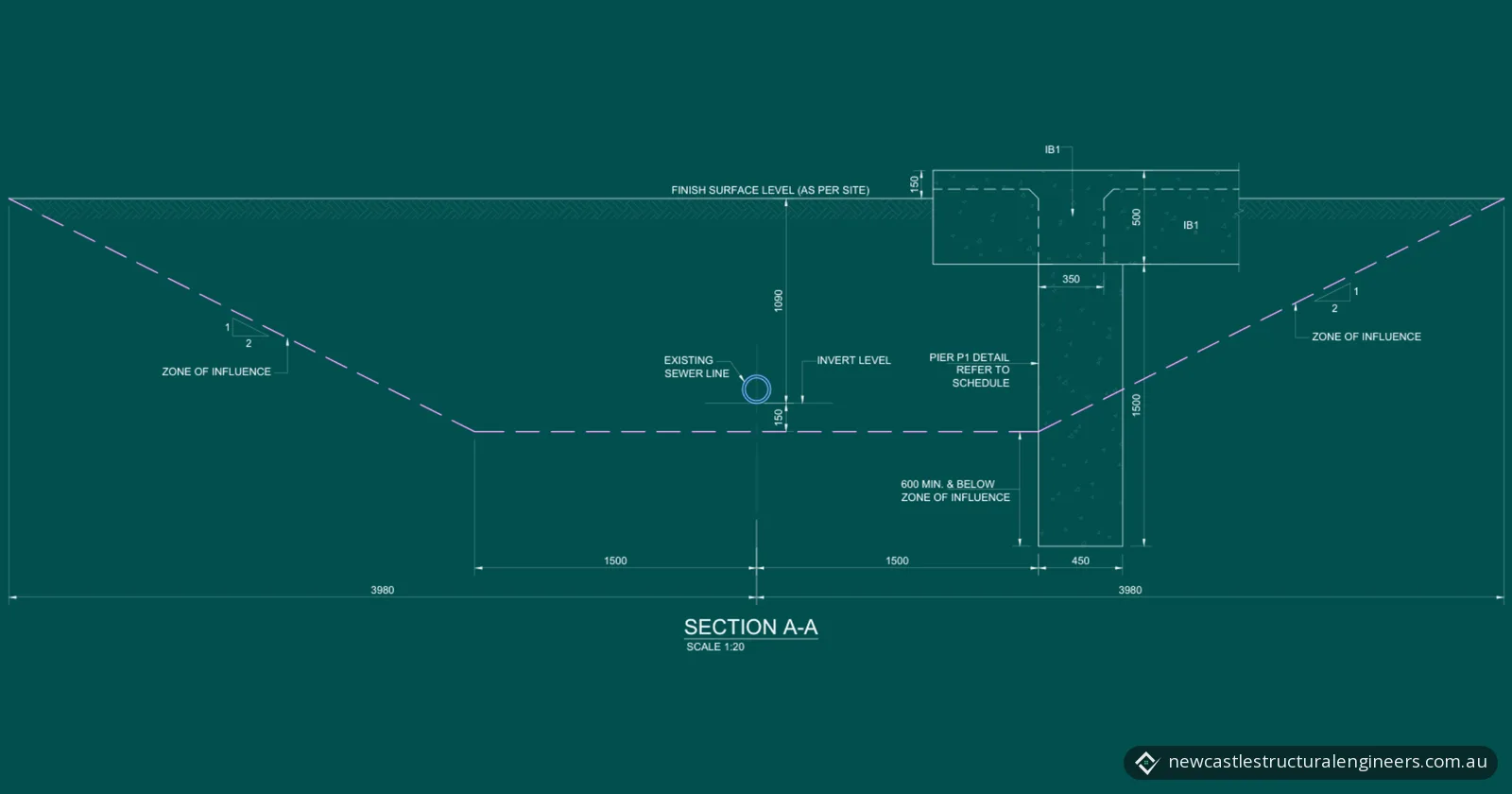
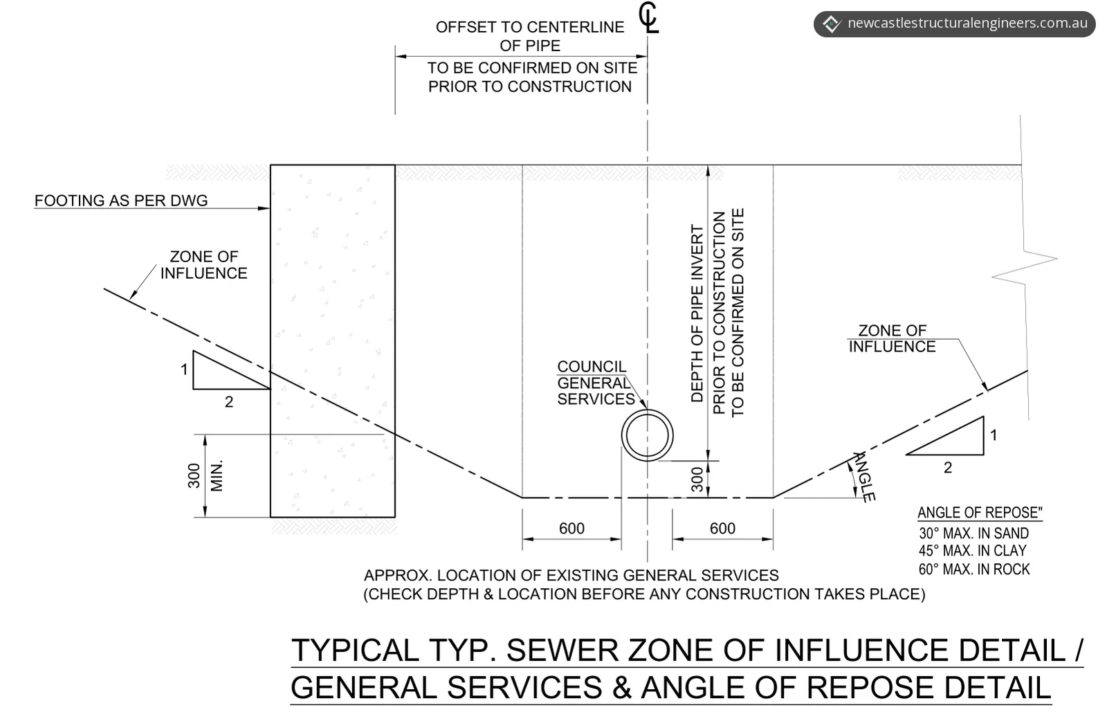
The new work also ties into the existing structure: new wall plates and timber beams are chemically anchored to it. The foundation plan shows an existing sewer line and an existing water main near the new footings, each with its zone of influence. Hunter Water's guidance says, as a general guide, to keep buildings and structures at least 1.5 metres away from its assets.
What we designed
We prepared a 19-sheet structural drawing set, from the demolition and foundation plans to the framing plans, connection details and a wall framing and lintel schedule.
- Ground. The design uses an allowable bearing capacity of 300 kPa at a depth of at least 1200 mm below natural ground level. Ground conditions can vary over a short distance, so footings are to be taken deeper as needed into stiff natural soil or rock of at least 300 kPa. If groundwater is found at the design depth of a beam, footing or pier, the engineer is to be contacted straight away.
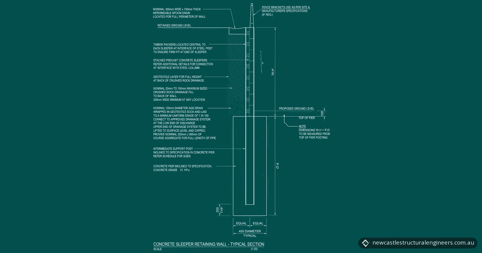
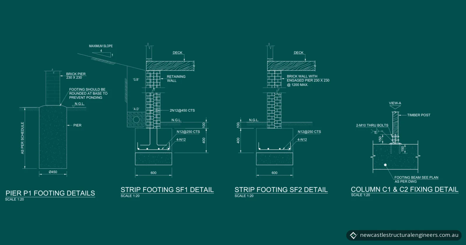
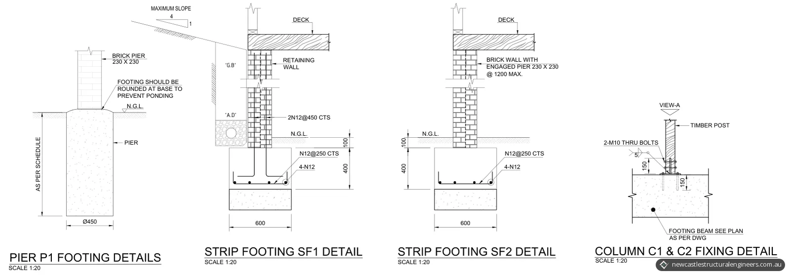
- Piers and strip footings. The P1 piers carry the brick piers under the new timber floor, and each footing should be rounded at the base of the brick pier to prevent ponding. The SF1 and SF2 strip footings are set 100 mm below natural ground level. SF1 carries a reinforced brick retaining wall with an ag drain behind it, and SF2 a brick wall with engaged piers at no more than 1200 mm centres.
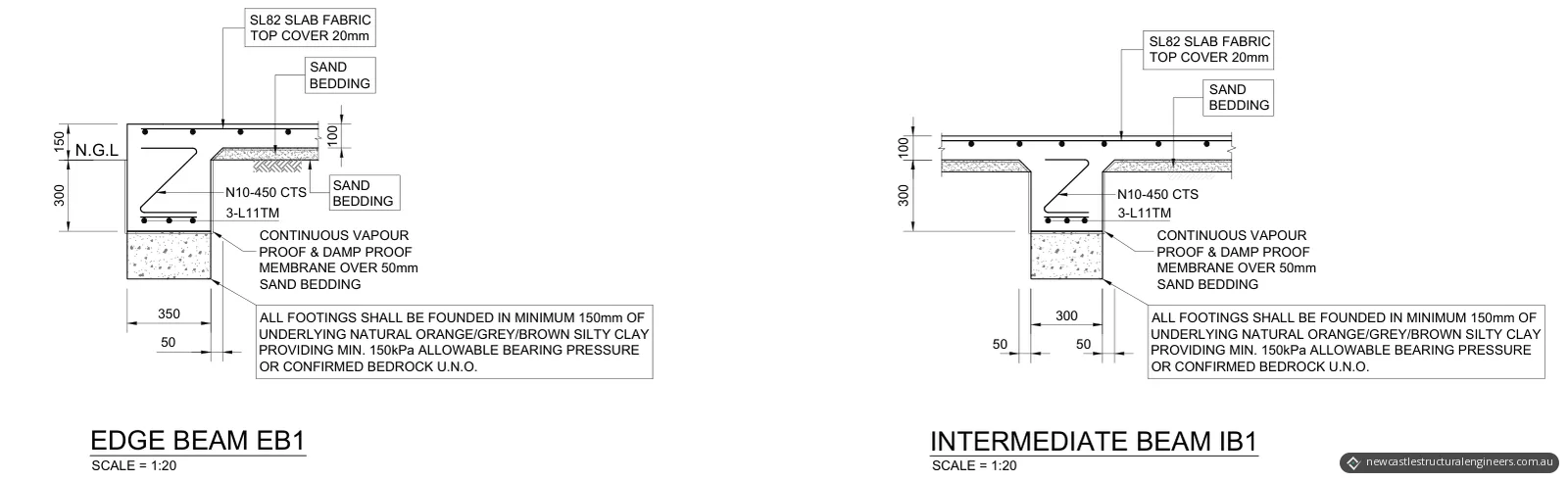
- Slab. The slab area is a 100 mm slab on ground with SL82 mesh at 20 mm top cover, on a continuous vapour-proof and damp-proof membrane over 50 mm of sand bedding. EB1 edge beams and IB1 intermediate beams stiffen it. These beams are founded at least 150 mm into natural silty clay of 150 kPa or more, or confirmed bedrock, unless noted otherwise.
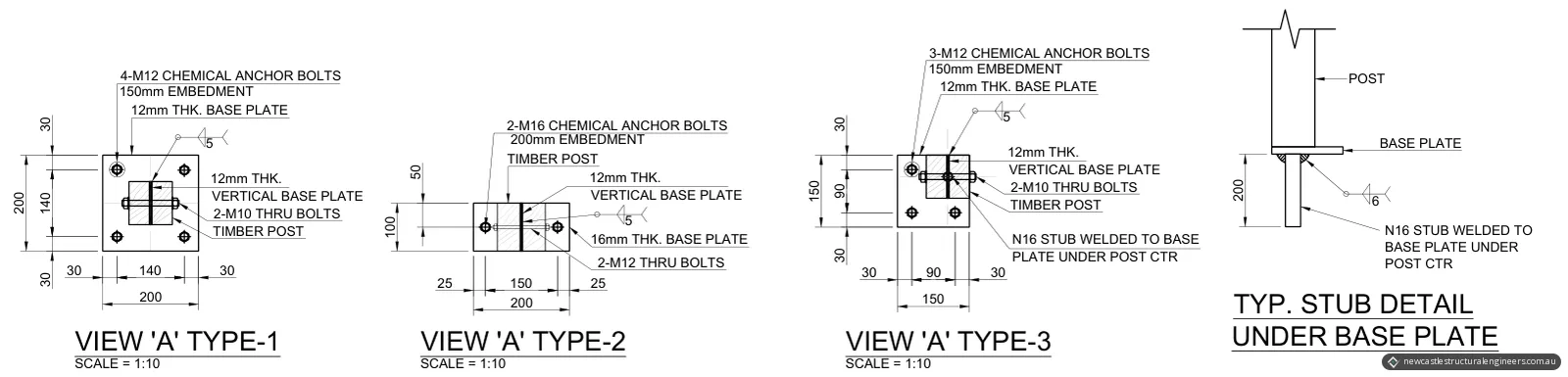
- Posts. Columns C1 and C2 stand on steel base plates chemically anchored into the footing beam. The drawings give three base plate options and a detail for an N16 stub welded under the plate at the post's centre.
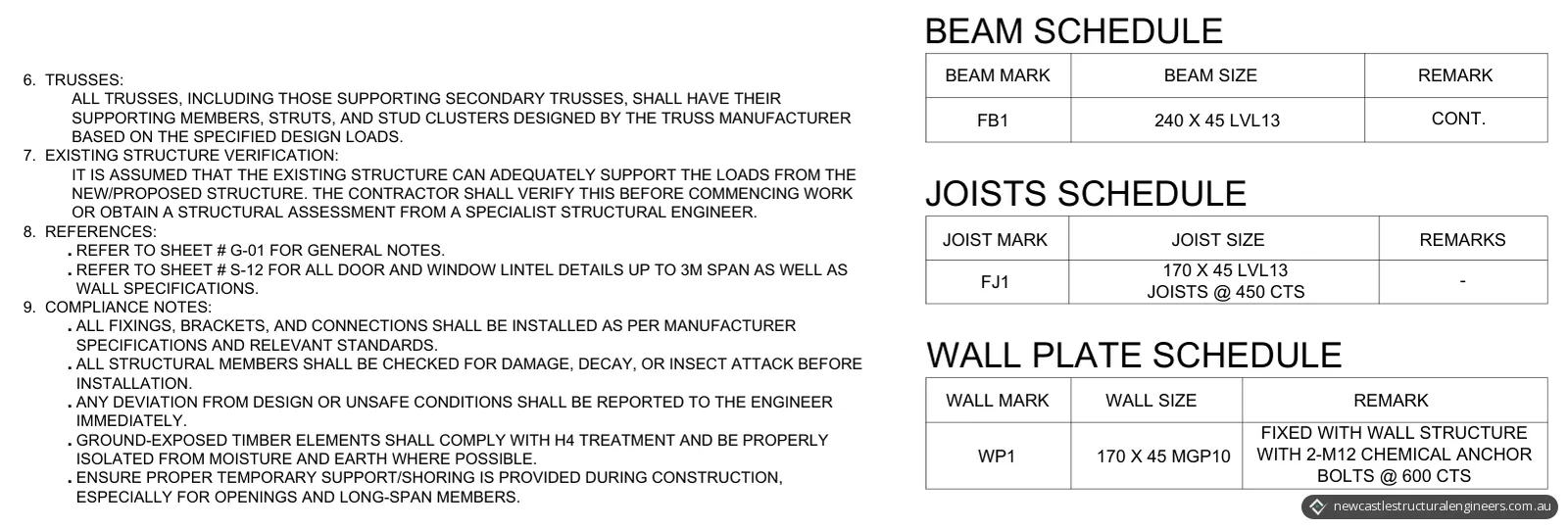
- Floor. The FB1 floor beams sit on the brick piers and carry the FJ1 joists. Where the floor meets the existing walls, WP1 wall plates are chemically anchored to the wall structure. Double joists go under load-bearing walls, point loads and studs.
- Roof. Trusses follow the manufacturer's specifications. Roof beams RB1, RB2 and RB3 carry the roof where the plan shows them; RB1 bears on triple studs (TS) and RB3 on double studs (DS).
- Walls and bracing. The site wind classification is N2. Type B structural plywood bracing panels are each at least 900 mm long, with M12 threaded rods either side of each bracing panel and each opening. The lintel schedule sizes window and door lintels by clear span, up to 3000 mm, and openings over 3.0 m get triple studs on each side.
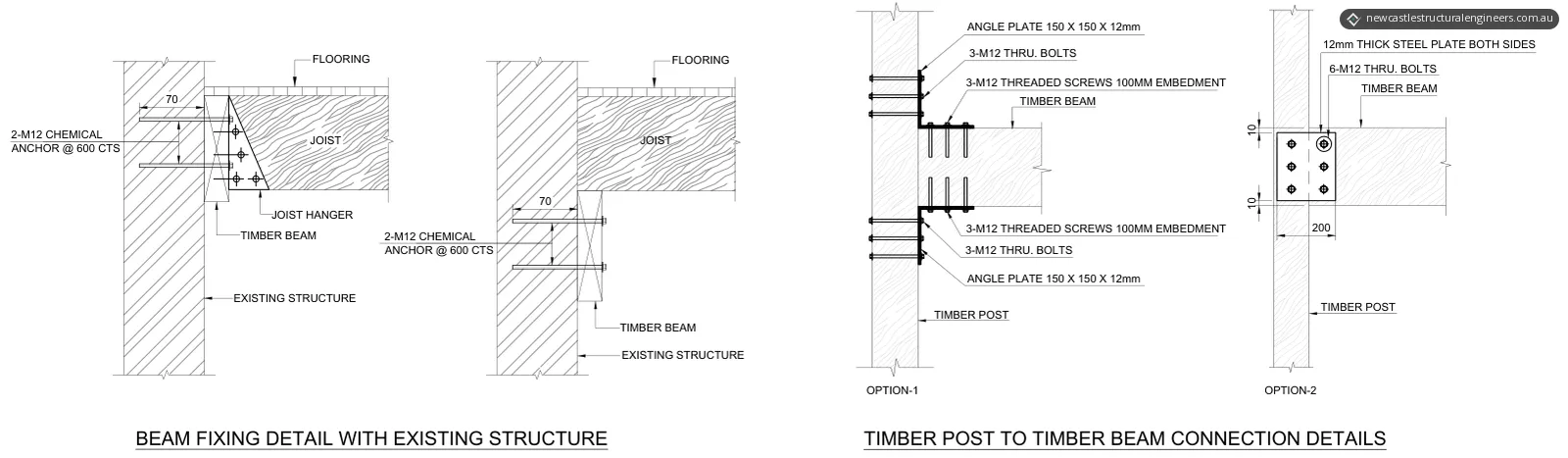
- Connections to the existing structure. New timber beams are fixed to the existing structure with two M12 chemical anchors at 600 mm centres, with the joists on a joist hanger or bearing on the beam. Timber posts connect to beams with 150 x 150 x 12 mm angle plates, or with 12 mm steel plates both sides and six M12 through-bolts.
- Pipes and services. The zone of influence detail takes a footing beside an underground pipe at least 300 mm below the zone of influence line. The pipe's depth and offset are to be confirmed on site before construction. Where a pipe passes through a footing, it goes through an oversize sleeve with compressible material, and the footing gets three additional cranked N12 bars. Our shed slab design beside a sewer in Tenambit shows piers taken below a sewer's zone of influence.
| Mark | Element | From the drawings |
|---|---|---|
| P1 | Pier footing | 450 mm diameter mass concrete, at least 1200 mm deep and down to hard strata |
| BP | Brick pier | 230 x 230 mm brickwork |
| SF1 | Strip footing | 600 mm wide, 400 mm deep, four N12 bars, under a brick retaining wall |
| SF2 | Strip footing | 600 mm wide, 400 mm deep, four N12 bars, under a brick wall with engaged piers |
| EB1 | Slab edge beam | 350 mm wide, three-bar L11 trench mesh |
| IB1 | Slab intermediate beam | 300 mm wide, three-bar L11 trench mesh |
| C1, C2 | Column | 100 x 100 mm hardwood timber post |
| FB1 | Floor beam | 240 x 45 mm LVL13, continuous |
| FJ1 | Floor joist | 170 x 45 mm LVL13 at 450 mm centres |
| WP1 | Wall plate | 170 x 45 mm MGP10, two M12 chemical anchors at 600 mm centres |
| RB1 | Roof beam | Two 240 x 45 mm MGP10 |
| RB2 | Roof beam | Two 300 x 45 mm LVL13 |
| RB3 | Roof beam | Two 190 x 45 mm MGP10 |
| DS, TS | Studs | Two or three 90 x 45 mm studs, resting on the frame or slab |
| RT | Roof truss | To the manufacturer's specifications, at 900 mm centres |
Concrete is specified at 32 MPa to AS 3600-2018 unless noted otherwise, and load-bearing brickwork at 40 MPa or more.
The result
Our client received a 19-sheet structural drawing set, revised once after their comments, with the demolition, footings, slab, floor, roof, bracing and the connections to the existing structure detailed. It gives the builder the member sizes, footing depths and fixings to work from.
The drawings also set out what has to be checked on site. The design assumes the existing structure can carry the loads from the new work, and the contractor is to verify this before starting work or obtain a structural assessment from a specialist structural engineer. The general notes ask the client to engage a geotechnical consultant to verify the foundation soil conditions before construction, and the builder to confirm all dimensions, existing conditions and obstructions before ordering materials. No responsibility is taken unless the work is inspected and approved during construction, and inspections are to be confirmed 72 hours in advance.
Planning alterations or additions around Newcastle?
Our structural design service prepares residential structural drawings for extensions and renovations, and alteration design for additions to existing structures. Send us your architectural plans, any geotechnical or soil report, and photos of the existing building where the new work will join it, and we'll give you a quote. Once building starts, our structural inspections service includes frame and construction stage inspections. Our service areas page lists the Newcastle suburbs we cover; if yours isn't listed, call us. You can request a quote online or call 02 4091 1900.
Photos and drawings
From the report
Sample pages from what the client received (personal details removed).
Frequently asked questions
Can alterations and additions to a home be complying development in NSW?
Yes, if they meet the Housing Code. The NSW Planning Portal says the Housing Code allows alterations and additions to a home as complying development when they meet the relevant development standards, including maximum building height, minimum setbacks and minimum landscaping requirements. The Housing Code only applies in zones R1, R2, R3, R4 and RU5. If a proposal can't meet its requirements, a development application has to be lodged with the local council.
What is a Class E site?
A Class E site is an extremely reactive clay site, which can experience extreme ground movement from moisture changes. That is the general definition in Table 4.2.2 of the ABCB Housing Provisions under NCC 2022. Clause 4.2.2 requires the foundations where footings and slabs are to be located to be classified in accordance with AS 2870.
Do I need Hunter Water's approval to build near a sewer main?
Possibly. Hunter Water's guidance says, as a general guide, to keep buildings and structures at least 1.5 metres away from its assets, and that it will assess your plans if your project is close to or over its pipes or assets. Depending on the project, you may need to submit a Build Over Asset Application. Its assets must stay accessible and can't be buried, demolished, relocated or altered without its approval.